The arguments of PMM constructors are almost always almost the same. Typically
they do not or only partially understand the physical basics behind their
machines. Here you will find some information how to analyze perpetual motion
machines. In order to keeps simple, mathematics will be used only on a very
basic level. Honestly spoken, math is not needed as long as we can explain
the non-workability of a machine by using basic principles.
Buoyancy Machines
I'm getting tired of checking buoyancy machines which are supposed to be
PMMs. The latest example was given by an inventor who sent me the URL of
his two patented machines, one dating from April 2003.
The idea of using buoyancy forces to keep a PMM moving is old and concepts
are abundant. There are two main classes of buoyancy PMMs which can be briefly
described as:
-
partly immersed system, with or without detachable masses.
-
completely immersed system, with or without detached masses, but with changeable
volume of the masses.
The Sophisticated Buoyancy Machine
I'd like to point out that I'm not willing to use formulae here, except a
few additions and subtractions. The flaw of a principle must be made obvious
without mathematics.
We focus on the second class of buoyancy machines, as they are more difficult
to understand. For the convenience of the reader and the benefit of the inventor,
we ignore frictional losses. A first drawing illustrates the machines' principle:
 |
|
Attached to a chain, several bodies with changeable volume are expexted
to move in, say counterclockwise direction. The volumes are:
-
V1 body sinks down
-
V2 body raises
The whole mechanism is completely immersed in a suitable liquid, e.g. water.
The mass of the bodies and the volumes V1 and V2 are
chosen in a way, that the abovementioned property holds. It is easy to understand
that the idea can work with any desired number of bodies, so it is sufficient
to analyze the way of one. A sort of circular process is expected to happen:
-
body has volume V1, therefore sinks down
-
body's volume is increased by an inner mechanism. New and larger volume is
V2
-
body raises
-
body's volume is decreased by an inner mechanism to volume V1
|
We assume that the mechanism inside the body works without losses of energy
(e.g. by friction) so that the two changes of volume add up to an energy
of zero. The conclusion is, as both steps 1 and 3 are caused by buoyancy
effects, the process should generate an excess of mechanical energy that
can be drawn for useful work.
This idea is very appealing and more than one patent has been issued for
machines of this kind.
Some readers might stop here and start building a perpetual motion machine
on this principle. I kindly ask them to read until the end of this page,
as they have a good opportunity to avoid frustration. In order to keep the
analysis as simple as possible, we look at several aspects of this mechanism
separately. By this, it should be easy to identify the "magic" portion of
the device or the process resp., which causes the generation of energy.
Circular Path of the Mass
First, we should have a critical look at the circular path of the mass. All
patents and suggestions of this class of machines which I know up to now,
assume that the path of the masses is closed and the shape, size or other
mechanical conditions of the mass are the same in the same location on its
path. As the liquid shall not be considered at the moment, we can easily
see that the movement of the mass fulfils the first law of thermodynamics,
which in this case can be interpreted as:
-
If a constant mass has been moved on a closed path in a gravity field, the
energy is zero.
By this, the mass and its closed path cannot be the reason of the expected
overunity behaviour of this PMM. As all these concepts claim that this behaviour
is caused by the buoyancy effect, we will look at it now.
The Up and Down Movements
First, we analyze the steps 1 and 3 of the circular path. We should remember
how buoyancy works: The forces acting on an immersed mass are generated by
the differences of pressure on top and bottom of this mass. If a mass sinks
or raises, the equivalent volume of liquid has to be forced to the place
in which originally the mass was located.
 |
 |
| Step 1: The mass sinks. By this, the equivalent volume V1
of liquid moves upwards. |
Step3: The mass raises. So the equivalent volume V2 of liquid
moves down. |
We can conclude, that by this the volume difference
V2-V1 moved down, whereas the mass itself returned
to the original height it had at the beginning of step 1. Obviously, by raising
of the body, a certain mass of liquid moved down without investing energy.
We have found the source of perpetual motion!
Did we?
The Volume Changes
Our analysis has ignored the steps 2 and 4, a point which is frequently
overlooked by inventors of these machines. Let's start the analysis in the
same way as we did with steps 1 and 3 before:
 |
 |
| Step 2: The liquid equivalent of volumes V2-V1
moves up |
Step 4: The liquid eqivalent of volumes V2-V1 moves
down. |
Our quick-minded inventor argues, that moving the constant volume up
and down will compensate, thus still leaving the result from or previous
analysis untouched. But slow down! We must be more careful!
We have ignored the work, that is needed to move the liquid. Let's regard
the liquid moving down in step 3 consists of the portions
V2-V1 and V1. It is easy to see, that the
V1 part exactly compensates the movement of the V1
part in step 1. Let's focus on the V2-V1 portion. We
see:
-
in step 2, the volume V2-V1 is moved by the height
h + g, which needs a certain amount of work
-
in step 3, the volume V2-V1 of liquid moves down by
h, thus providing some work.
-
in step 4, the volume V2-V1 of liquid moves down by
g, thus again providing some work
Now we have pushed the liquid mass equivalent to
V2-V1 up by h+g, then moved it down by h and g. The
resulting energy sum is zero. What is the conclusion of this lenghty discussion?
We have proved that the easily ignored steps 2 and 4 i.e. changing of the
volumes are the key to understanding the flaw in this machine. Sorry. No
perpetual motion machine!
The Simplest Explanation
Remember the first law of thermodynamics? Remember the sentence a few lines
above:
-
If a constant mass has been moved on a closed path in a gravity field, the
energy is zero.
Which masses are involved in this circular process?
-
The mass of the immersed body. We've already found out that this particular
mass on its circular path has an energy bilance of zero.
-
The mass of the displaced liquid. When the immersed body retuns to the same
position at the same volume (whichever) on its closed path, the same volume
eqivalent (=mass equivalent) has also moved on a circular path to its original
position. We see, that the energy bilance is zero as well.
We can add zero energy as long and often as we want, the result will never
become positive. Even if the discussed machine is initially set into motion,
it soon will stop, as there are losses by liquid friction, which we have
neglected up to now.
If you are interesed in a more detailled discussion of unworkable buoyancy
machines, have a look at Donald Simanek's
site
on buoyancy misconceptions. If you see any parallelities in ideas, do
not worry! For sure this is no sign for the great conspiration
but rather for scientific collaboration and understanding of basic concepts
in physics.
Translation ongoing!
About efficiency
The pure confusion! Sometimes I get the impression that every author writing
about unity, overunity and efficiency has a different understanding about
these basics. The confusion can be undone by a few simple definitions.
| Definition: |
|
Wirkungsgrad. |
|
|
| Remarks: |
|
Im englischsprachigen Raum finden sich folgende Begriffe:
-
Unity ist Wirkungsgrad 1
-
Overunity ist Wirkungsgrad > 1
|
Basic Assumptions
| Assumptions: |
|
For our theoretical considerations, we agree on these assuptions:
-
Bearings without friction (idealized bearings)
-
Air resistance will be neglected
-
Point masses
-
Newtonian mechanics, slow motion (less than 0.1c)
-
All units in SI system
-
The proof of the non-operability of a PMM must not be made by the argument
of the unavoidable friction losses, but by the principal flaw in the idea.
|
Levers and Torque
The classical PMM i.e. the overbalanced wheel is based on levers and unbalanced
masses. The principle of these machines is based on the law of levers.
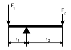
Lever in equilibrum
F1 ´ r1 = F2 ´ r2
where a single torque M = F ´ r
. That means a torque is the product of the applied force at a certain radius
from the rotational center of the lever.
If the lever shall remain in equilibrum, the condition is that the sum of
all torques adds up to zero. If this sum is not zeor, the lever starts to
rotate in the direction of the resulting torque. Let's have a closer look
at a typical overbalanced wheel.
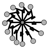
Lever-based perpetual motion machine
This device can be started into any desired direction, but it will cease
running after a short while. It was expected that due to the asymmetric
arrangement of masses, a permanent unbalanced torqu should result. So does
the law of levers not apply here? It does. The inventor has missed some important
points:
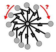 |
|
1. |
Auf der linken Seite sind zwar die Hebel kürzer, aber die Anzahl
der Massen größer, so daß insgesamt die Momente ausgeglichen
werden können. Ich schreibe hier bewußt können, denn
es gibt viele Stellungen der Maschine, in der die Momente nicht ausgeglichen
sind. Bewegt man das Rad in eine dieser Positionen, so bewirkt das einseitige
Drehmoment, daß sich das Rad in einen Gleichgewichtszustand bewegt.
Könnten die Lagerreibung und andere Störeinflüsse ausgeschlossen
werden, würde der Mechanismus ewig oszillieren, genauso, wie er ewig
rotieren würde, wenn er mit genügend Schwung angeworfen wird. Im
Sinne der Definition ist das aber kein PM!
In welche Richtung soll dieses Gerät bevorzugt laufen? Nach rechts,
wegen der längeren Hebel? Oder nach links, wegen der größeren
Anzahl Massen? |
| |
 |
|
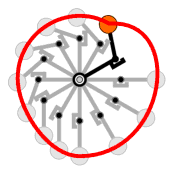
2. |
Für das Drehmoment ist nicht der radiale Abstand der Masse
zum Drehpunkt von Bedeutung, sondern ausschließlich der Abstand
zwischen der senkrecht wirkenden Kraftlinie und dem Drehpunkt. Hier unterliegen
viele Laien oft demselben Trugschluß wie der Konstrukteur dieser
Fahrradtretkurbel um 1900. So ist bei senkrecht nach unten in C
angreifender Kraft der wirksame Hebelarm der Abstand A-C und nicht
A-B. |
| |
 |
|
3. |
Der Energieerhaltungssatz gilt für die Massen in dieser Maschine.
Wenn man den Weg einer einzelnen Masse betrachtet, dann vollführt sie
einen zyklisch geschlossenen Weg. Und in seiner allgemeinen Form kann der
Energieerhaltungssatz in seiner Ausprägung als Potentialsatz so formuliert
werden: Wird ein Körper im Gravitationsfeld
auf einer geschlossenen Bahn zum Ausgangspunkt zurückbewegt, ist die
dafür aufgewendete Arbeit = 0.
Anders ausgedrückt: die Arbeit, die durch die Bahn einer Masse auf der
rechten Seite des Rades gewonnen wird, ist exakt die Arbeit, die notwendig
ist, um dieselbe Masse wieder auf der linken Seite des Rades auf die
ursprüngliche Höhe anzuheben. Die Anzahl der Arme, die Drehrichtung
und die Momentangeschwindigkeit der Massen haben deshalb keinerlei Einfluß
auf die (Nicht-)Funktionsweise! |
Rolling Ball Machines, Recirculation Mills
 |
|
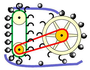
PM, deren umlaufende Massen aus Kugeln oder einer bestimmten Menge Wasser
bestehen, lassen sich mit dem Argument 3 aus der vorherigen Betrachtung
widerlegen. Auch hier gilt der Energieerhaltungssatz für das umlaufende
Medium, egal ob es sich dabei um eine Flüssigkeit handelt oder um Kugeln.
Der Verlauf des Weges spielt bei der Betrachtung keine Rolle. |
Springs
Springs normally obey Hooke's law under the condition that a suitable material
is used for the spring and the range of linear force-distance will not be
left. Already at school, Hooke's law is introduced by this experiment:
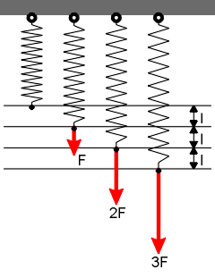
Spring at different load forces
The elongation l of the spring is directly proportinal to the applied force
F. The measure of the elongation is the so-called spring constant, which
depends from material and type of spring. Hookes law is given by
D = DF / Dl = const
Springs can store enery, so they find wide usage in all technical areas.
Springs always have a positve constant. Of course not every material can
be characterized by Hooke's law (e.g. rubber). In general, different materials
have typical "kennlinien".
Recently, somebody suggested a spring with negative constant "it must be
a spring, which needs les and lkess force when stretched". What do you think?
Honestly spoken the springs in my workshop do not behave that way.
But that shall not prevent us from analyzing this idea.
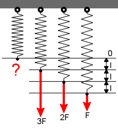
A reverse-proportional Hookeian spring
We see, the spring is stretched a small load and contracted at high load.
Briefly, the spring operates in exactly the reverse way than a standard Hookeian
spring. I cannot give a reasonalble assumption for an unloaded spring of
this type; maybe it is stretched to its maximum length? (but hardly infinite
length)
We should keep in mind that in every system which is in static equilibrum,
Newton's second law of mechanics holds, so action equals reaction.
With a spring of the "reverse type" we can build a nice machine...
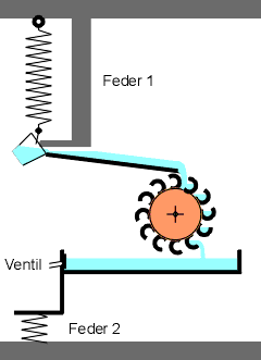
Wassermaschine mit umgekehrt-hookescher Zugfeder 1
und hookescher Druckfeder 2, die das Ventil betätigt
Die Funktionsweise ist schnell erklärt. Wir beginnen mit einem leichten,
also leeren Eimer. Die Feder 1 ist gedehnt, der Eimer betätigt
durch sein Eigengewicht ein Ventil und wird aus dem Wasserreservoir gefüllt
, wodurch er schwerer wird. Weil der Eimer schwer ist, zieht sich die Feder
1 zusammen und befördert den Eimer nach oben. An der oberen Rinne
wird der Eimer durch einen Kippmechanismus geleert und damit wieder leicht.
Das Spiel kann sich von vorne wiederholen. Das in die obere Rinne
beförderte Wasser dient zum Antrieb einer Kraftmaschine.
Fazit: das ist ein PM, das offenkundig den Satz über die Erhaltung der
Energie verletzt (siehe oben). Das Potential, das
der gefüllte Eimer am oberen Punkt hat, ist höher, als das des
gefüllten Eimers unmittelbar nach dem Füllen. Die Feder verrichtet
also Hubarbeit. Aus welcher Kraftquelle speist sich die Feder?
Am Besten, wir vergessen das Ganze und bleiben bei den üblichen Federn.
Ein paar typische Einwände hört man immer wieder.
| Einwand 1: |
|
Es gibt doch Materialien, wie z.B. Blei, die sich bei zunehmender Streckung
mit immer weniger Kraft immer weiter dehnen lassen! |
| Antwort: |
|
Stimmt. Es handelt sich bei Blei oder bei Plastilin um (nahezu)
vollständig plastisch deformierbare Materialien, bei denen die gesamte
Arbeit, die man zum Strecken aufbringt, durch innere Reibung in Wärme
umgesetzt wird. Eine Federwirkung - und damit Energiespeicherung - ist nur
bei sehr begrenzten Wegen vorhanden.
Man lasse sich aber durch die abnehmende Gesamtkraft nicht täuschen,
denn wichtig für die Betrachtung ist die Kraft pro Querschnittsfläche,
die aufgebracht werden muß. Und die nimmt bis kurz vor dem Bruch
geringfügig zu. |
|
|
| Einwand 2: |
|
Was ist mit Potentialfeldern? Schwerkraft oder elektrische Anziehungskaft
nehmen quadratisch mit dem Abstand der beteiligten Objekte ab? Das ist doch
ein nichtlinearer Zusammenhang mit abnehmenden Kräften bei zunehmendem
Abstand? |
| Antwort: |
|
Stimmt. Aber Potentialfelder sind keine Federn. Das hindert nicht daran,
daß in Potentialfeldern der Energieerhaltungssatz Gültigkeit hat.
Das Thema Schwerkraft werde ich gelegentlich näher
abhandeln... |
Aufmerksame Leser werden bemerken, daß ich sie mit der Feder ein wenig
aufs Glatteis geführt habe. Ich kann mir sehr gut Modelle von
Federn vorstellen, die andere Kraft-Weg-Verläufe haben, wie die
idealisierten hookeschen Federn aus dem Schulunterricht. Letzten Endes ist
es vollkommen nebensächlich, wie eine "Feder" von ihrem inneren Mechanismus
her arbeitet. Genaugenommen ist jeder Gegenstand auf irgendeine Art eine
"Feder". Läßt man z.B. eine Kugel am Ende eines Stabes rotieren,
so kommt die Gegenkraft im Stab, die verhindert, daß die Kugel
fortgeschleudert wird, durch die Federwirkung des Stabes zustande. Wenn wir
ein wenig weitergrübeln, können wir uns ein dynamisches Federmodell
erarbeiten:

| Nr. |
Bauteil |
1 |
Anhängeöse |
2 |
Akkumulator |
3 |
Kraftsensor |
4 |
Microcontroller/Regler |
5 |
Elektromotor-Generator-Kombination mit
Haltebremse |
6 |
Seilrolle |
7 |
Längemeßeinrichtung |
8 |
Lastöse |
Wie funktioniert diese Black-Box-Feder? Wie jede andere Feder wird sie mit
den Ösen 1 und 8 an den Versuchsaufbau angehängt. Der Motor 5 kann
die Seilrolle 6 in beiden Richtungen bewegen. Wird das Seil herausgezogen,
lädt der Motor als Generator den Akku 2. Um das Seil mit einer bestimmten
Kraft einzuholen, wird aus dem Akku gespeicherte Arbeit entnommen. Der Regler
4 wertet die Zugkraft, die mit dem Sensor 3 gemessen wird und die abgerollte
Seillänge (Längenmessung 7) aus und steuert entsprechend den
Betrieb des Motors. Bei konstanter Zugkraft wird die Haltebremse aktiviert,
sodaß der Motor die Last nicht "aktiv" halten muß. Der Regler
kann über eine geeignet vorgegebene Kennlinie, die einem Kraft-Weg-Diagramm
entspricht, die Zugkraft im Seil entsprechend der abgerollten Länge
beeinflussen.
Das Federmodell hat gegenüber einer realen Feder einen Nachteil: wird
nicht viel Gehirnschmalz in den Regler gesteckt, dann lassen sich Schwingungen
nicht verwirklichen.
Mit diesem Federmodell kann offenbar jede Federkennlinie verwirklicht werden,
auch die vorhin erwähnte "inversen". Setzen wir voraus, daß
Motor/Generator und Haltebremse verlustfrei arbeiten und daß der Akku
genausoviel Elektronen hergibt, wie zuvor hineingepumpt wurden. Dennoch kann
ein Perpetuum Mobile mit dieser Feder nicht gebaut werden. Der Grund sollte
klar sein: die Arbeit, die der Feder entnommen wird, entstammt dem Akkumulator
als Energiespeicher. Wird in der Gesamtbilanz mehr entnommen, als
zurückgespeist wird, ist der Akkumulator irgendwann leer.
Mechanische Federn können ebenfalls Energie speichern. Doch geben sie
nicht mehr her, als sie gespeichert haben...


