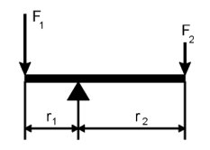
Lever in equilibrum
F1 ´ r1 = F2 ´ r2
| Every formula will scarce 1000 readers
away Old proverb You are visitor number 1! Welcome! Author |
We will use these facts in the following chapters about perpetual motion machines.
The pure confusion! Sometimes I get the impression that every author writing about unity, overunity and efficiency has a different understanding about these basics. The confusion can be undone by a few simple definitions.
| Definition: | Efficiency or coefficient of performance. | |
|---|---|---|
|
|
|
|
| Remarks: | In english-speaking countries, often these terms are used:
|
|
| Assumptions: | For our theoretical considerations, we agree on these assuptions:
|
|---|
It is useful to have a clear concept about these basic expressions and their meanings. Frequently enough, machines are claimed to have some properties, only because the inventor confuse force with power or impulse with energy.
y
y
y
y
The classical PMM i.e. the overbalanced wheel is based on levers and unbalanced masses. The principle of these machines is based on the law of levers.

Lever in equilibrum
F1 ´ r1 = F2 ´ r2
where a single torque M = F ´ r . That means a torque is the product of the applied force at a certain radius from the rotational center of the lever.
If the lever shall remain in equilibrum, the condition is that the sum of all torques adds up to zero. If this sum is not zeor, the lever starts to rotate in the direction of the resulting torque.
A whole book could be written of machine elements and machinery. This had been done many times, so I'm not going to repeat what can be found elsewhere. But I'd like to draw your attention to some facts, which are frequently regarded as less important by amateur inventors or when analysing technical systems. A particular object of interest are gears.
For sure, you have already seen images of cogwheels and gearboxes. Or you may have visited an old mill, where the gears are exposed to the spectator. Gears are abundant in machine construction and laymen normally don't have any idea, what happens inside a gearbox. Engineers know that gears are very sensitive for inaccuracies in their geometry and they wear out rapidly, if they are not precisely machined.
 |
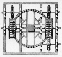
In old mills, this type of gears can be found. Because of the shape of the construction elements, they are called lanterns and pinions. Before gears systematically were under research, they were made by practicioners. Often a carpenter made the work, whereas very fine gears were made by clockmakers. Gears for water wheels and mills were crude, did not fit exactly and needed care and repair work. Their efficiency was sufficient at their times, but compared to today's modern precision gears, it was lousy. | |
 |
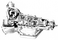
Compare this 3-speed automatic gearbox from 1963 with the image above!
The main difference is not only complexity, but completely different types
of cogs, precisely machined parts, a cast housing, roller-bearings, oil-filling,
sealings etc. And: this is a mechanical construction made in mass production
at prices, at which the gear above cannot be built by a skilled craftsman. Although modern gears work at high efficiency, automotive engineers have to take into account that some horse powers remain in the gearbox, thus heating it up. |
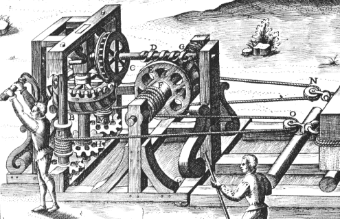
This machine drawing is part of a plate from the famous book by Agostino Ramelli. It is no perpetual motion machine, but intended as a winch for very heavy loads. Take this as an exercise to analyze a complicated mechanism! Do you think this machine is workable at all? Does it contain flaws that make the construction less plausible? Into which direction must the operator turn the crank in order to pull the load closer to the machine? Can the whole task be solved in an easier way?

From plate no. 180 of Le diverse et artificiose machine
Ramelli has given far more complex mechanisms. This one is of intermediate
level.
We should keep in mind that Ramelli wanted to impress his readers by demonstrating the skilful combination of many machine elements in order to create a new device of unheard capabilities. Often enough, Ramelli did more effort than was good for his designs. A careful analysis of his machines shows that most of them would work in the indended way, but that some are of little practical value. An operator would dislike to turn a crank a thousand times to lift a load by an inch! (c.f. Ramelli, chapter 177) In this example, fortunately this is not the case. If you are sufficiently confused, you may want to check my solution.
Flywheels are a construction element that is important to store energy either for a short while to compensate irregularities in the rotational speed of a shaft (which can be found even in today's modern combustion engines) or to store energy that is fed in over a long period of time and then used in a short time interval.
| Last update: 22 May 2004 / |
|